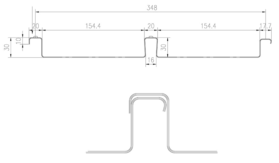
FD350 Formwork Spaning Tables
These results have been developed from testing results provided by GCE Consulting whom managed a series of tests on various lengths and thicknesses of the FD350 profile at Swinburne University, Victoria. Utilising these derived section properties, design tables for the FD350 Deck have been developed for the formwork stage of construction considering a number of base metal thicknesses based on strength and deflection criteria.
Flexural Stiffness
The Flexural Stiffness for the sheeting has been derived from testing of the deck profile under both single and multiple span configurations with varying spans and thicknesses. The modulus of elasticity (E) of the steel sheeting is assumed to be 200,000MPa and yield strength (fy) of the sheeting is assumed to be 500MPa. The stiffness of the profile is affected by the length of the span and the number of spans. For the development of the spanning tables the stiffness is defined by the following equations for both the single and multiple spans.
Single Spans – Flexural Stiffness
Ief/tbm = 41.35L + 70600 mm4/m/mm
such that 140300 <= Ief/tbm <= 165600 mm4/m/mm
Multiple Spans – Flexural Stiffness
Ief/tbm = 37.2L + 63300 mm4/m/mm
such that 106000 <= Ief/tbm <= 149040 mm4/m/mm
In both cases L is the free span of the of the decking and the thickness of the base metal (tbm) and measured in millimetres.
Assumed Strength
The design moment capacities are determined from the testing for both the positive and negative bending, along with the shear capacity and presented in the table below.

Formwork Tables
The flexural stiffness and strength results listed above are utilised in the development of the following design tables. For multiple spans the negative moment of the sheeting is considered under an ultimate and serviceability limit state assuming redistribution once the
moment capacity over the support is exceeded. In the following tables where the shear capacity or the negative bending under self-weight at the middle supports governs the spans are highlighted in italic and bold. These span – depth combinations are highlighted as local deformations at propping locations may be visible after pouring. In the development of the spanning tables an allowance for concrete ponding due to sheet
deformation has been included and the concrete density has been assumed to be 2400Kg/m3. The other loadings included in the development of the tables are the dead load resulting from the sheeting and construction live load allowances which are determined in accordance with Australian Standards AS1170, AS3610 and AS2327 as outlined for Stage 2 loading. These load cases included a 4kPa loading over the middle third of the span, and an additional 2kPa loading at mid span with the corresponding concrete self-weight. Live loading from Stage 1 are significantly lower than the construction loads and thus do not govern.
While concrete ponding due to deflection of the sheeting has been considered, mounding of concrete above finished concrete levels should not occur. In the development of the tables mounding based on a number of varying load cases has been considered. If mounding is considered to be necessary, a suitably qualified person should assess the locations, to minimise both the permanent deflections and loads imposed on the decking.
It is assumed that multiple spans are poured simultaneously to ensure deflection limits are maintained..
It is assumed that the support widths are 50 mm at sheeting ends and 75 mm over intermediate supports.
Concentrated loading should also be avoided at the sheet overlap joints and unsupported edges.
The tables assume that when using two or more spans the adjacent lengths of spans do not vary by more than 5% and that maximum spans are not exceeded. The tables have been developed on the basis of the mechanical properties of the sheeting alone, consequently the capacity of the composite action has not considered in these tables.
Table 1 – 1.0 mm Base Metal Thickness ‐ Deflection Limitation L/150

Table 2 – 1.0 mm Base Metal Thickness ‐ Deflection Limitation L/240

Table 3 – 0.9 mm Base Metal Thickness ‐ Deflection Limitation L/150

Table 4 – 0.9 mm Base Metal Thickness ‐ Deflection Limitation L/240

Table 5 – 0.75 mm Base Metal Thickness ‐ Deflection Limitation L/150

Table 6 – 0.75 mm Base Metal Thickness ‐ Deflection Limitation L/240


